X-Ray Diffraction
X-Ray Diffraction Notes that cover both general and advanced level. Also includes notes on Neutron Diffraction, EXAFS, etc.
X-ray Diffraction Notes
Space Lattice & Unit Cell
Crystal – ordered array of atoms or ions in which a pattern or motif is repeated periodically in 3D. Specification of 3 chosen axes together with the corresponding identity periods (point chosen that is reproduced at regular intervals) defines a space lattice. This subsequently defines the unit cell as a member of the set of parallelepipeds into which the lattice is divided by the axes.
X-rays interact with a crystal such that a diffraction pattern is produced due to the internal periodicity of its structure.
Directions of diffraction depend on the space lattice only, while intensities depend on the nature and arrangement of scattering material within the unit cell.
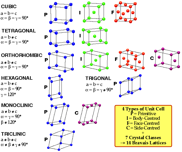
3D Unit Cells and Bravais Lattices
Unit cell of 3D lattice is a parallelepiped defined by 3 distances (a,b,c) and 3 angles (α,β,γ).
Also, 4 types of 3D unit cell:
Primitive (P) – one lattice point.
Body Centred (I) – lattice point at each corner + one in centre.
Face Centred (F) – lattice point at each corner + one in centre of each face.
Face Centred (A,B,C) – lattice point at each corner + one in centre of one pair of opposite faces, e.g. A-centred → lattice points in bc faces.
4 types of lattice and 7 possible unit cells gives rise to 14 permissible Bravais Lattices (only 14 due to some of the symmetry requirements, e.g. no A-centred cubic – only 2 of 6 faces are centred then cubic symmetry is lost).
They are shown below:
Labelling of Lattice Planes – Miller Indices
Plane passing through 3 non-collinear lattice points is called rational. A rational plane may be described by a set of Miller Indices (h,k,l). They define a plane cutting the x, y and z axes at (1/h, 1/k, 1/l) respectively.
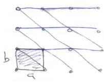
2D regular lattice from unit cell of sides a,b.
Can distinguish planes by the distance at which they intersect a and b axes.
Could quote smallest intersection distances, e.g. the above black lines as (1,1), but blue would be (∞,1). Fractions are also possible, and that along with infinity signs makes this method inconvenient.
It is eliminated by taking the reciprocal, which gives Miller Indices (h,k,l).
e.g.
(1,1, ∞) → (1,1,0)
( ½,⅔,∞) → (2,3,0)
This has further advantages later on as well.
Helpful to remember that the small h, k or l are, the more nearly parallel the plane is to the a, b or c axis respectively (i.e. 0kl planes are parallel to the a axis).
Generation of X-rays
Discovery of X-rays in 1895. Electrically heated filament, usually Tungsten, emits electrons which are accelerated by a high potential difference and allowed to hit a metal anode which is water-cooled. Anode emits a continuous spectrum of X-radiation with superimposed sharp, intense X-ray peaks (Kα, Kβ). Frequencies of Kα, Kβ characteristic of anode, which is usually Cu or Mo.
X-ray Sources:
- High voltage discharge tube with Cu(1.54 Å) or Mo(0.71 Å) anode. Stray X-ray lines removed by filters or monochromating crystals.
- Synchrotron. Very bright, very monochromatic, very expensive.
Powder Diffraction:
Random crystallites. A few accidentally satisfy the Bragg condition for each hkl plane. Set of conical rings at angle 2θ to the incident beam. Detect with film or counter.
Uses of Powder Diffraction:
- Determine unit cell parameters.
- Analysis of mixtures of phases. Common solids are fingerprinted in a database.
- High Temperature solid state synthesis.
Single crystals are very rare (do not melt or dissolve). Reflections overlap so not enough are resolved to solve complex structures.
Powder Techniques
3 principal methods.
a) DeBye-Scherrer Camera.
Very small quantity of finely-ground powder is mounted on greased glass capillary tube and rotated in an X-ray beam. Reflected beams = cones of semi-angle 2θ.
Cones produce series of arcs (lines) on film.
Suffers from lack of resolution (short film length) and shifts of lines at low angle (due to absorption).
Cu source filtered with Ni to remove Kb (λ = 1.39Å) in a 2:1 ratio. This gives splitting of lines at high angle.
b) Guinier Focussing Camera
undistorted high resolution powder photograph. Monochromated X-ray and set at Bragg angle to give only Kα1. Good for accurate lattice parameters.
c) Powder Diffractometry.
No photographic methods – intensity measured with a Geiger-Muller counter. Plot intensity vs. 2θ.
Bragg angle reflects only Kα1 and Kα2. Similar resolution to Guinier Camera but more sample needed. Is fast and gives peak intensities.
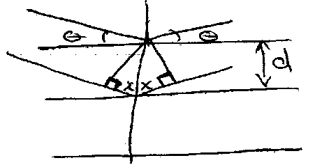
Bragg’s Rule
Diffraction of X-rays by a crystal can be treated in terms of reflection from sets of lattice planes. Although electrons of individual atoms scatter the X-rays, ordered atomic planes makes the scattering coherent, i.e. which produces a reflected beam which obeys the simple law of optics for reflection from a plane mirror. This is:
2x = nλ
→ 2d sin θ = nλ
where d = interplanar spacing. This is Bragg’s Rule.


Worth remembering that sin2 θ =

NB: the angle between the incident and reflected ray 2θ is used when data is plotted.
Relating the d and unit cell parameters
For a square unit cell:

In 3D:

Also, for tetragonal unit cells: ao = bo ≠ co,

And for orthorhombic unit cells: ao ≠ bo ≠ co,

Other low symmetry or non-orthogonal lattices can be derived, but are complicated.
Angle θ at which reflection can occur is determined solely by lattice symmetry and unit cell parameters using Bragg:

A reflection should thus be observed for each possible value of (h2+k2+l2).
|
hkl |
h2+k2+l2 |
Multiplicity |
|
100 |
1 |
6 |
|
110 |
2 |
12 |
|
111 |
3 |
8 |
|
200 |
4 |
6 |
Multiplicity – reflection will occur at same value of θ for all permutations of a given set of hkl. Thus, (100), (010), (001), (00), (00), (00) all have same spacing and contribute equally to the intensity. Hence, multiplicity = 6. Note that this only applies to the cubic case, if it were tetragonal then h = k ≠ l, so the multiplicity is altered.

Unit Cell Considerations
Primitive: h,k,l integers allowed (h2+k2+l2 = 1,2.3…, but not 7 – requires non-integers)
BCC: h+k+l = even (h2+k2+l2 = 2,4,6 …)
FCC: h,k,l all odd or all even (h2+k2+l2 = 3,4,8,11,12 …)
Consider 2 adjacent BCC cells. 100 planes interleaved by another layer of atoms. When x-rays diffracted by the 100 plane are in phase, those diffracted by the interleaved atoms will be of exactly opposite phase, since interleaved atoms are half-way between each pair of 100 planes.
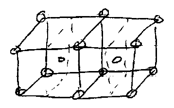
Hence, over the whole lattice, 100 is absent. 200 is not though, so appear (all atoms lie in this family of planes). Similarly, all atoms contribute to (110).
However, a better way of explaining these absences is to use the Structure Factor (i.e. the Intensity). See below for details.
Indexing
Cubic Systems
Simplest, and least number of reflections as 100 = 010 = 001 etc.
Since , successive values of sin2 θ will bear simple ratios to one another. Having ascertained these ratios by comparison to h2+k2+l2 values, each value of sin2 θ can be assigned values for h, k and l. This is indexing. Can then calculate ao.

Can find out the number of atoms per unit cell when the density is known using this, by calculating the volume of the unit cell and using:
ρ = , where z is the number of atoms per unit cell.

Expect z = 1 for Primitive, z = 2 for BCC, and z = 4 for FCC.
Cubic Table
|
Forbidden |
Primitive |
FCC |
BCC |
Indices |
|
|
1 |
|
|
100 |
|
|
2 |
|
2 |
110 |
|
|
3 |
3 |
|
111 |
|
|
4 |
4 |
4 |
200 |
|
|
5 |
|
|
201 |
|
|
6 |
|
6 |
211 |
|
7 |
|
|
|
|
|
|
8 |
8 |
8 |
220 |
|
|
9 |
|
|
221, 300 |
|
|
10 |
|
10 |
301 |
|
|
11 |
11 |
|
311 |
|
|
12 |
12 |
12 |
222 |
|
|
13 |
|
|
320 |
|
|
14 |
|
14 |
321 |
|
15 |
|
|
|
|
|
|
16 |
16 |
16 |
400 |
|
|
17 |
|
|
401, 322 |
|
|
18 |
|
18 |
330,441 |
|
|
19 |
19 |
|
331 |
|
|
20 |
20 |
20 |
420 |
|
|
21 |
|
|
421 |
|
|
22 |
|
22 |
332 |
|
23 |
|
|
|
|
|
|
24 |
24 |
24 |
422 |
|
|
25 |
|
|
430, 500 |
|
|
26 |
|
26 |
431, 501 |
Remember that there can be additional absences in addition to those above. Usually due to:
- Intensity too weak to measure.
- Screw axes and glide planes of symmetry in the structure.
Glide Plane
Combines translation with reflection. Reflection through a plane of symmetry, then translate in x or z direction (plane is xy) by half the repeat distance.
Screw Axis
Translation with rotation. Translational distance = i/n for a screw axis ni, e.g. 21 along z → introduce plane of atoms exactly half-way between 001 planes – reflections from these destructively interfere with the 001 and so these are absent.
All the required absences must be present for FCC or BCC, otherwise it is primitive.
Tetragonal Systems
Lattice translation along one axis differs, such that:

i.e.
sin2 θ = A (h2+k2) + C l2
Hence, there will be additional peaks as, for a given (hkl), there will be permutations that have different l values, and hence different sin2 θ.
Also, ao and co can be very different, so there is no fixed order for the indexing.
Intensities
Bragg’s Rule gives only the geometrical condition for a reflection.
Intensity is a function of several factors, some of which depend on experimental technique employed and others on the solid.

L(θ) is a trigonometrical factor, = (1+cos22θ) / (sin2θ cosθ)
ρ is the multiplicity factor, e.g. (321) comprises 48 separate reflections which in a cubic crystal appear at the same angle (as discussed earlier). Would split 321, 312, 213 for tetragonal (different l).
A = absorption factor. Function of the Bragg Angle. Sometimes heavier atoms absorb X-rays instead of scattering them.
The Structure Factor
Fhkl(θ) =

Because the sine term is an odd function of the coordinates it vanishes for centrosymmetric structures. Because centrosymmetric structures are common, usually only the cosine part is required.
For any hkl the scattered amplitude is the sum of amplitudes from all the scattering atoms, added together with the appropriate phase.
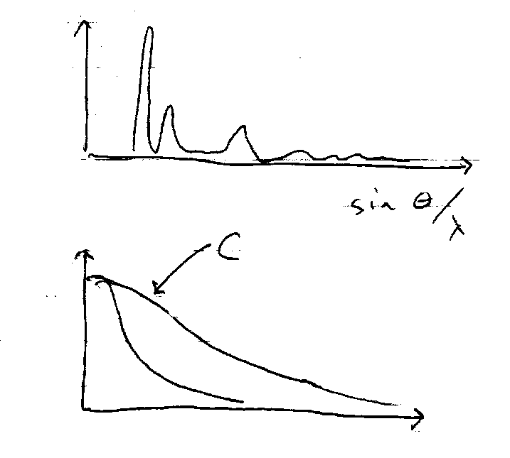
The scattering power of individual atoms, fn(θ), decreases steeply with increasing θ, but increases almost linearly with atomic number as more electrons scatter so heavy atoms dominate the scattering. Intensity concentrated at low θ.
Systematic Absences:
These occur because the relative phase of scattering from equivalent atoms can differ by π, leading to destructive interference. In the FCC lattice there is an atom at (0,0,0) and the same atoms at (1/2,1/2,0), (0,1/2,1/2) and (1/2,0,1/2). If we calculate Fhkl for the (hkl) = (100) reflection, the phase factor cos 2π (hx + ky + lz) for the atom at (0,0,0) is +1, but that at (1/2,1/2,0) is -1. For (0,1/2,1/2) it is +1 and for (1/2,0,1/2) it is -1. The sum of all these is zero, so there is no intensity in this reflection. Rules like this depend on the translational symmetry, as embodied by the 14 Bravais lattice types, and depend on the presence of bond-centering, face-centering. Screw axes and Glide planes also generate absences.
Cases to remember –
Reflections are permitted if:
FCC – hkl all even or all odd
BCC – h+k+l is even
Remember that CsCl is NOT BCC because the Cs is not the same a Cl!!!
KCl is FCC but appears primitive with a smaller cell, because K+ and Cl- are isoelectronic and have almost identical scattering power.
Temperature Factor
Atomic scattering factors are derived from electron distributions of atoms at rest. At ordinary temperatures, thermal vibrations of the atoms will cause them to occupy a larger volume than they would at rest and will make scattering still smaller.
The scattering factor f compares to one at rest as:
f = fo exp [-B sin2 θ / λ2], where B varies for different atoms in the same crystal, and depends on direction.


Electron Density Distribution (i.e. Crystal Structure)

From the intensities Ihkl we know | Fhkl | but not its phase (+1 or -1 in centrosymmetric structures). Solving this phase problem is difficult. Methods use:
- the Patterson Function
- Isomorphic replacement of heavy atoms.
- So-called “direct methods”.
Optimisation or Refinement of the structure involves adjusting the atomic parameters to minimise the standard deviations between Icalc and Iobs sum over all hkl.
How much data is needed?
It takes 9 parameters to define an atom, 3 for its centre (xyz) and 6 for its vibrational amplitude represented by an ellipsoid. Structures are often represented in diagrams illustrating these. The ellipsoid is specified by 3 principal axes, but 2 angles are needed to define the spatial orientation of (say) the longest axis, and a further angle is needed to define the orientation of the other axes relative to the long axis. So it needs at least 9 (but more like 20 in practice) independent observations to define each independent atom. With an X-ray tube source the width of a reflection is 0.5o in units of 2θ.
With powder data many different reflections are superimposed along a single 2θ axis and they overlap. Note much useable data beyond 2θ = 60o, so typically < 150 reflections can be resolved. This can only locate ~ 8 independent atoms, and is only useful for very simple structures. Narrower linewidth of a synchrotron increases the amount of data and allows solution of more complex problems. The Reitveld refinement method uses sensible shapes for each reflection to partially overcome the problem of overlapping peaks.
Single Crystal reflections are spread out over a sphere, and don’t overlap (4-circle diffractometer). Modern instruments replace the counter by a large “area detector” which can detect all the reflections simultaneously – a massive increase in speed. A typical data set might contain 6000 reflections. Not all are independent, since their intensities can be related by symmetry. Thus structures with < 150 atoms should be solvable.
Neutron Diffraction
Neutrons from a nuclear reactor are slowed to “thermal velocities”. Their peak wavelength is then ~1.5Å. They are monochromated by chopping the neutron beam to let through only a narrow range of velocities. Neutrons are mainly scattered by nuclei. The scattering probability is therefore very low compared with X-rays, but the scattering amplitude is:
- independent of 2θ
- similar for light and heavy atoms.
Neutrons also have a magnetic moment, and can be diffracted by interaction with arrays of ordered electronic magnetic moments.
Advantages of Neutrons:
- Can locate light atoms in the presence of heavy atoms (e.g. D in CeD2, or H-bonding problems), or distinguish those of similar atomic number if scattering amplitudes differ (Ni and Co in Ni2CoO4 spinel).
- More high angle (large 2θ) data compared to X-rays eases structure determination, especially for powders.
- Locates nuclei so if spherical electron density is superposed on these positions, X-ray diffraction can show (by difference) the electronic deformation density due to bonding.
- Can map unpaired electron density. Shows arrangement of spins in ferromagnets and antiferromagnets (e.g. extra peaks in FeO below the magnetic ordering temperature – super-lattice formation), and delocalisation of spin from metal orbitals in transition metal compounds (direct indication of covalency).
- Zr containers are transparent to neutrons, so easy to work at low temperature (X-rays strongly absorbed, so window materials difficult).
Disadvantages of Neutrons:
Too few available. Low scattering amplitude requires large sample, and long data collection times. Especially difficult to grow large enough single crystals for complex structures.
Electron Diffraction
50KeV electrons have λ ≈ 0.05 Å. Strongly scattered. Mostly used for diffraction in low pressure (10 Torr) gases to measure molecular dimensions, but also in the electron microscopy on very thin solid sections. Use differential pumping to allow scattered electrons to reach detector (film). Data is a series of intensity fringes, which can be Fourier transformed into a radial distribution curve, which has peaks for every pairwise distance within the molecule. Good for accurate bond lengths and angles, in fairly complex molecules where for example microwave rotation spectra are too difficult to interpret. Must be volatile, i.e. covalent molecular species of limited RMM, e.g. FeCp2, WME6, and non-metal compounds.
EXAFS (Extended X-ray Absorption Fine Structure)
This experiments is only used with amorphous non-crystalline materials, when ordinary diffraction methods are not applicable. It provides data on the number, nature and distance of the immediate neighbours of a chosen atom (usually a metal). It uses the synchrotron as a source of monochromatic X-rays whose wavelength can be scanned.
As the X-ray photon energy is increased it becomes sufficient to excite a core electron to empty valence shell orbitals. At this point the absorption probability rises, and structure appears in the spectrum. This is called X-Ray Absorption Near Edge Structure, and has some useful chemical content. When the energy reaches the photoionisation limit the absorption probability rises sharply.
Thereafter it decreases smoothly, because the overlap of the free-electron wavefunction (whose wavelength is becoming shorter) and the atomic wavefunctions become smaller. In a monatomic gas, this sharp rise, followed by a gradual fall, is all that is observed. In a molecular species the outgoing electron wave can suffer interference from waves scattered backwards from neighbours. As the wavelength of the ionised electron becomes shorter, the phase relationship changes, and this affects ionisation probability, increasing it when the waves are in phase and decreasing it when they are out of phase. The result is a set of interference fringes superimposed on the absorption spectrum. The phase relationship depends on the distance of the back-scattering atom. The fringe positions therefore contain data on the interatomic distances, while the intensity depends on the type of atom that back-scatters. The experiment thus looks outwards from the atom whose edge is selected, and reports on its neighbours within about 5 Å.
Most applications are in complex biological molecules that don’t crystallise, or in catalytic species absorbed on surfaces of supporting solids.
I am happy for them to be reproduced, but please include credit to this website if you're putting them somewhere public please!