Advanced Solid State
Only covers the topics I chose to study for - namely Synthesis, Intercalation, Ruddlesden-Popper Phases, Superconductors and Zeolites
Advanced Solid State Chemistry Notes
Synthesis of Solids
Synthesis of solids has two major problems associated with it –
- Low mobility of ions.
- Large activation (bond breaking)
Both of these are resolved by using high temperatures, which means that the thermodynamic product is always formed. This has consequences associated with it, in terms of Phase Diagrams, shown below.
Traditional Ceramic Synthesis
This involves grinding powders of simple binary solids together, and pressing into pellets. These can then be reacted together at a high temperature to make a more complex solid. This route is often inefficient because the reaction only occurs at the surfaces, so repeated grinding is required. That said, it is useful because it is so simple. This is the method that would be used to prepare spinels from two solid binary compounds, or high temperature superconductors (lab).
The advantages are that it is technically undemanding, and gives good crystalline products. The problems are that it is slow and requires high temperatures (usually 800-1700oC).
The reaction environment may need to be controlled if a particular oxidation state or reaction stoichiometry is required. In such cases the reactions are carried out in a controlled atmosphere, using a tube furnace, where a particular gas can be passed over the reaction mixture during heating.
Another problem encountered in direct synthesis is the volatility of one or more components of the mixture at the high temperatures required for reaction. In such cases the reaction mixture is normally sealed in a glass tube, under vacuum, prior to heating. This would likely by necessary for the formation of VS2 from V + S2, as the sulphur is volatile at the reaction temperature and would be lost from the reaction mixture in an open vessel, leading to impure products.
Sol Gel and related Syntheses
This helps to overcome the inherent problem with solid state synthesis that the diffusion is extremely slow in the solid state, and this leads to poor mixing on the atomic scale. Thus it is often the case that the product is inhomogeneous, or cannot be made in a single phase.
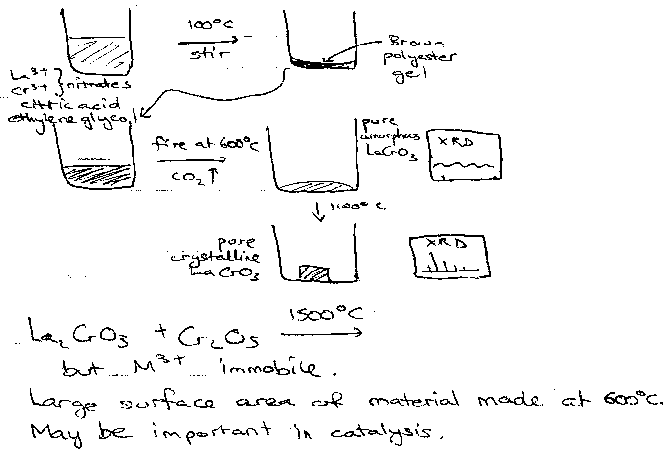
The alternative is to mix the metal ions in solution, chelate them with citric acid and ethylene glycol and form a polyester gel on evaporation. This has the metal ions mixed on the atomic scale in the solid state. This citrate gel may then be fired at temperatures much lower than required in ceramic synthesis.
Crystal Growth
This is particularly useful for forming a single crystal, which can then be analysed more easily and effectively than a powder (which forms from the above two methods). In fact, single crystals are often required for the full evaluation of the physical properties of a material.
Crystal growth of molecular solids from a suitable solvent is routine. Non-molecular solids require more careful technique.
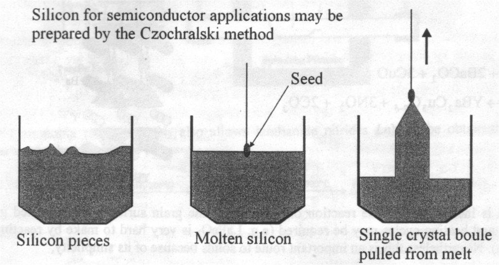
Melt Growth – if the material melts congruently (i.e. if the melt and the solid have identical compositions) crystal may often be grown by slowly cooling the melt. Related techniques for growing large crystals are important for certain technological applications. These include the Czochralski and Bridgman techniques. Here one needs an awareness of phase diagrams to know whether such an approach is feasible (see below).
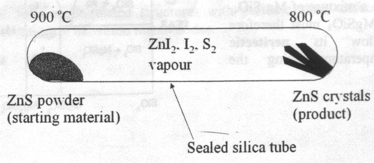
Vapour Transport – useful for volatile solids (or those that produce volatile molecules). It involves transporting along a temperature gradient. The classic example of this is transport of ZnS using I2, where ZnS powder is transported as ZnI2 + I2 + S2 down a temperature gradient to form crystals of ZnS at the other end. This forms at the cooler end because the reaction to form ZnI2 is endothermic (equilibrium constant falls as the temperature decreases).
ZnS can be transported by iodine by virtue of the equilibrium:
ZnS(s) + I2(g) ⇌ ZnI2(g) + S2(g)
The gaseous products act as transport agents for Zn and S. Since this reaction is endothermic, the equilibrium constant, and hence the partial pressures of ZnI2 and S2, will decrease as the temperature decreases. Thus at the cooler end of the tube, ZnS will tend to crystallise. The temperature regime should be chosen such that the equilibrium constant for the reaction is small, transport to the cooler end then takes places at a slow enough rate that high-quality crystals form (a few mg per hour).
Flux Growth – incongruently melting solids or those which sublime/decompose before melting can often be grown at temperatures well below these temperatures by dissolving them in a flux (like a solvent). The problem here is the risk of incorporating this flux compound into the product. Halide melts are commonly used for synthesis of oxides and sulphides.
An example is the synthesis of Barium Titanate. BaTiO3 is grown from a 2.5 fold molar excess of KF, to which Fe2O3 is added. The melt is heated in air at 1200oC for several hours to dissolve the BaTiO3, cooled to 900oC and the molten flux is then poured off the BaTiO3 crystals which have formed during the cooling phase. A small amount of incorporated Fe3+ compensates for the slight loss of oxide as oxygen at high temperatures.
Gallium Nitide, GaN, is a wide band gap semiconductor which is used in thin film blue LED and laser devices. Single crystal GaN would be a good substrate for such films, and small single crystals have been grown recently from a molten Na/Ga melt held under 100atm pressure of N2 at 750oC. Many nitrides can be grown in this way. Na3N is thermodynamically unstable wrt the elements above 260K, so there is no contamination. The Na/Ga (and also Na/alkaline earth) melt solubilises an as yet poorly-characterised nitrogen-containing species.
Chimie Douce Methods – Intercalation
This is a useful way of modifying the properties of solids at low temperatures. Intercalation is the insertion of an atom/ion/molecule into a host compound, while leaving the structure of the host largely unchanged (this means it is topotactic). It usually changes the properties greatly though.
Low Temperatures –
- less structural organisation.
- Products which may be unstable at high temperature.
- Can obtain greatly modified properties
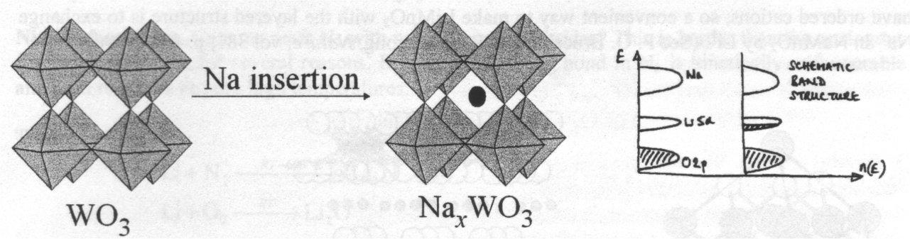
Reductive intercalation (usually with alkali metals) involves inserting the alkali metal cation into a suitable site, while the electron from this enters the conduction band of the solid. The requirement for this is an open structure so that the metal can fit in, and also it must be reducible.
Layered Sulphides can also be intercalated into. This is because of their greater tendency to form layered structures. Early Transition Metal Sulphides are particularly appropriate because they are often reducible. An example of this would be e.g. inserting Na into TiS2. This can be achieved by using n-BuLi, Lewis Base (e.g. ammonia) and the alkali metal vapour. It should be noted here that insertion of Li into TiS2 is reversible, which is the principle behind Li-ion batteries.

Intercalation into fullerenes is simple because of the large cavity space available. Crystalline C60 has a CCP structure and is a good oxidising agent. The classic example is reacting it with potassium vapour to yield K3C60, with K+ occupying all the octahedral and tetrahedral holes in the array. This conducts well due to orbital overlap between adjacent molecules and the electrons occupying the narrow bands.
Intercalation into Oxides does not require this layered structure. The classic example of this are the tungsten bronzes, NaxWO3.
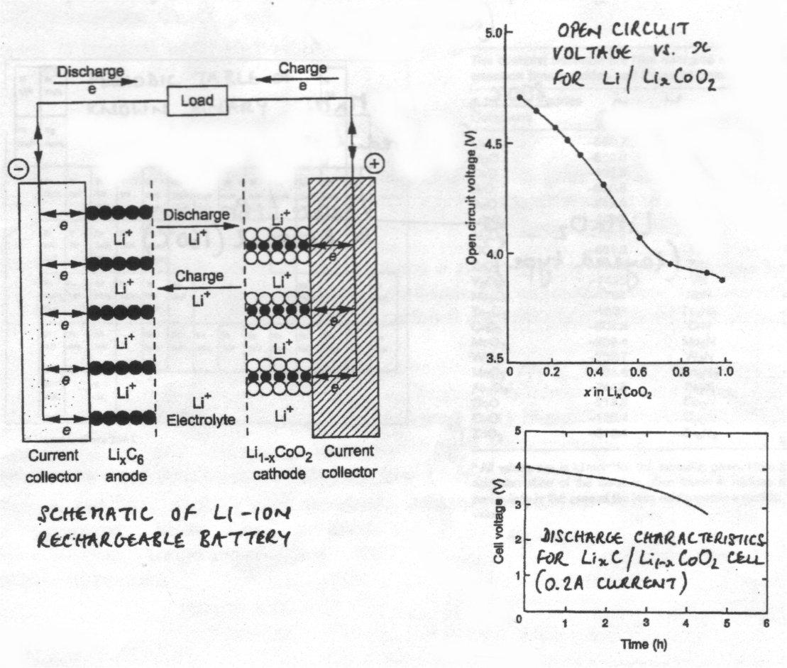
Electrochemical Intercalation / Deintercalation into Oxides – Li-ion Batteries
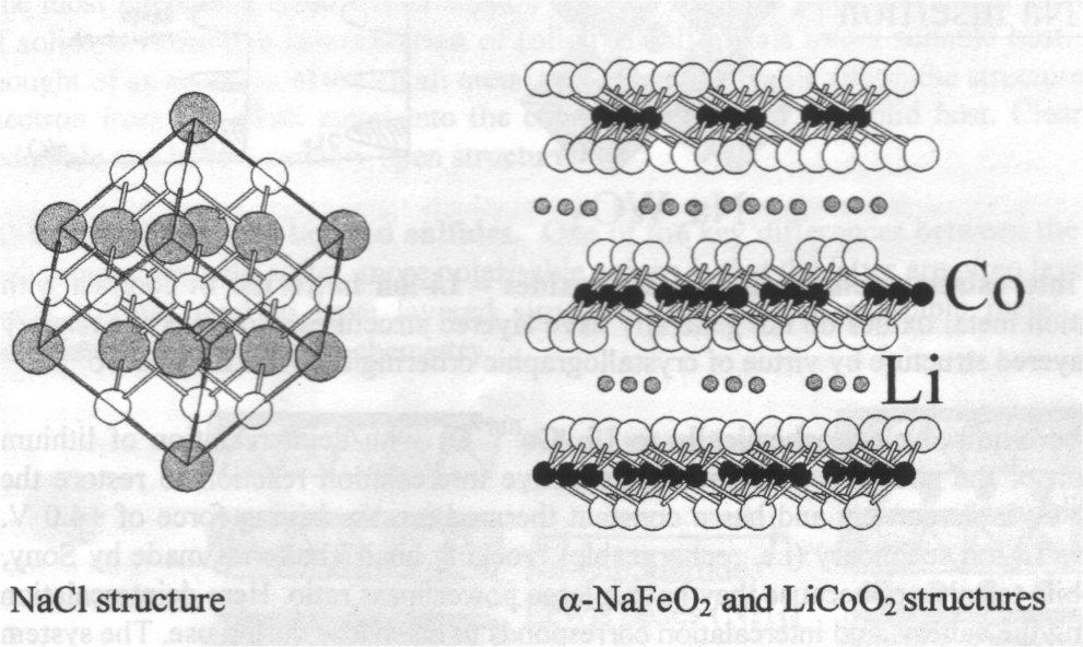
In contrast with sulphides, binary transition metal oxides do not generally have layered structures. However, the ternary LiCoO2 does by virtue of crystallographic ordering between Li+ and Co3+. Light elements → high energy density.
This compound can be oxidised electrochemically to Li0.5CoIII/IVO2 with deintercalation of lithium metal, but preservation of the structure. The reverse reductive intercalation reaction to restore the composition is favourable and has a constant thermodynamic driving force of +4V. This is the basis of the Li-ion secondary (i.e. rechargeable) batteries, which are used in mobile phones as they have a large power/mass ratio. Here deintercalation corresponds to charging the battery, and intercalation corresponds to discharge during use. The system is highly reversible.
It is possible to deintercalate Li completely to make CoIVO2, but the increase of power density and voltage is at the expense of poor cyclability due to collapse of the structure.
Ion Exchange
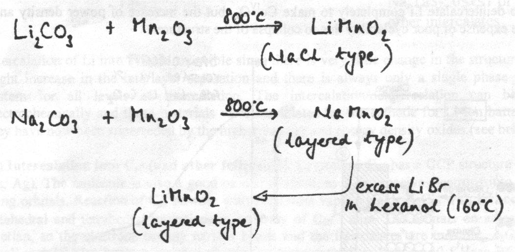
LiMnO2 with a layered variant of the sodium chloride structure is another important oxide in battery technology. Reaction of Li2CO3 with Mn2O3 at high temperatures (800oC) yields LiMnO2 but, in contrast with the LiCoO2 case above, the material has disordered MnIII and Li+ in the sodium chloride structure. NaMnO2 synthesised in this conventional way does have ordered cations, so a convenient way to make LiMnO2 with the layered structure is to exchange Na+ in NaMnO2 by Li+.
LiMnO2 can be produced in both these structure types:
On paper, Mn appears to be a more attractive Li-ion battery, as it can delivery similar power with a full range of reversibility and greater capacity, as well as being cheaper and less toxic. However, MnIII d4 undergoes Jahn-Teller distortion from octahedral geometry, which greatly hampers the reversibility – break down of the electrode structure after many cycles.
Solid + Gas Reactions using a Reactive Atmosphere
The reactive atmosphere may be O2 – many metals will oxidise in air or oxygen to form their oxides. Many metals react with sulphur vapour to form sulphides. Basic oxides such as BaO react with atmospheric CO2 to form the carbonate.
Nitride formation – reacting N2 with metals to form nitrides. Harder than analogous formation of oxides for several reasons. Breaking the strong N2 bond is kinetically unfavourable, and such reactions require high temperatures.
Furthermore, breaking the N2 bond and ionising N to N3- are large thermodynamic costs which may not be reclaimed by form M-N bonds in the solid. If high temperatures are employed to give reasonable reaction rates, the gaseous N2 is favoured entropically, and many nitrides are thermodynamically unstable wrt the elements at high temperatures.
Gallium Nitride, mentioned above, is thermodynamically unstable with respect to the elements above 1000oC. Ga is unreactive to N2 below this temperature. A more reactive N source is required for the synthesis of GaN than for the nitrides of the more reactive alkaline earths and lanthanides. There are two routes to the bulk powder in which flowing ammonia gas reacts with the element or its oxide (both require 700oC):
Ga + NH3 → GaN + 3/2 H2
Ga2O3 + NH3 → GaN + H2O
GaN has the wurtzite structure.
Reduction of Oxides
Reduction using a gas is a common way to make reduced transition metal oxides. A huge range of reduced titanium and vanadium oxides may be obtained in this way. These have a range of unusual structural and electronic features (e.g. Peierls Distortion).

V2O5 VO2


VO2 VnO2n-1 (n>3) Magneli Phases V2O3


Solution and Hydrothermal Methods
Many non-oxide inorganic materials may be synthesised by crystallisation from solution. This is extended by using hydrothermal techniques where the reacting solution is heated in a sealed vessel above its boiling point. Such reactions are important in the synthesis of open structure zeolites. The preparation of zeolites typically involves crystallisation from a strongly basic aqueous solution containing the tetrahedral structure building ions plus a templating ion that is frequently an organic base. The shape of the templating ion directs the crystallisation of the aluminate and silicate tetrahedral and determines the structure of the zeolite product. The crystallisation process is frequently slow and hydrothermal methods act to speed up the process.
Phase Diagrams
An important factor to consider when trying to synthesise a solid is the phase diagram of the various components in the reaction. The direct reaction of components to form inorganic materials is generally carried out below the melting point of the system despite the process being extremely slow. Ideally we would want to use molten phases to increase the rate (rapid ion diffusion). The problem is that this molten mixture usually doesn’t yield the desired product in a pure form.
Phase diagrams illustrate the behaviour of multi-component systems as a function of temperature by delineating the ranges of stability of various phases in terms of the stoichiometry of the mixture and the temperature.
The diagram to the left is a simple two component system with the x axis denoting the relative proportions of two components A and B and the y axis the temperature. A and B do not react together (i.e. no AB compound in the system). An example would be CdO and CuO. The four regions of the diagram are:
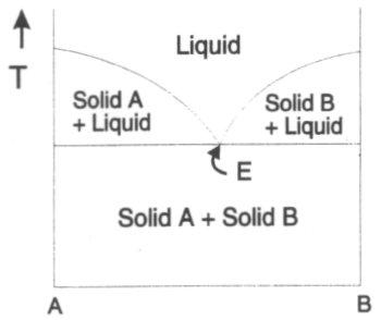
Low temperatures – both A and B are solids and a mixture of the two consists of discrete particles of the two solids.
Higher temperatures – A and B melt, and depending on the stoichiometry, regions occur where solid A exists with a liquid, solid B exists with a liquid or the whole system is molten.
The point E (lowest temperature where the whole system is liquid) is the eutectic point.
This information is more useful for reacting systems, such as the following:
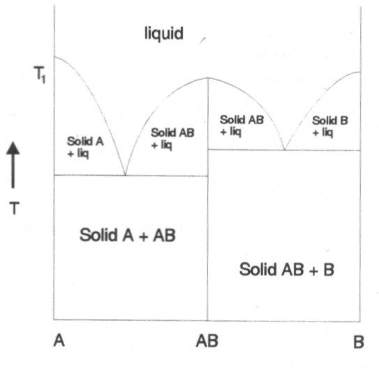
In this case the components A and B react together and form a compound of stoichiometry AB with a different structure. This new compound is represented by a vertical line. A feature of this is that if AB is heated then on reaching T1 it melts to form a liquid of the same composition. This is congruent melting.
Another type of phase diagram that occurs for two component systems is as follows:
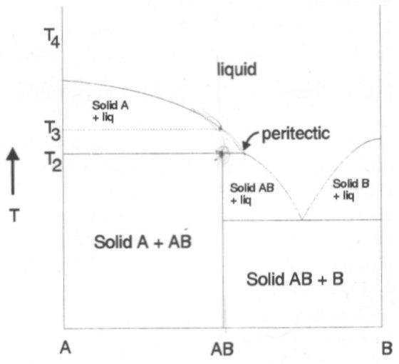
Heating AB up to T2 only partially melts to yield some solid A plus a liquid that is richer in B. On further heating the solid A dissolves in the liquid until at T3 the system is completely molten with composition AB. When AB does not melt directly to give a liquid of the same composition, this is known as incongruent melting. This has profound effects regarding synthesis.
Phase Diagrams are particularly significant when carrying out solid state synthesis. Precise temperature and composition are required (examples). This has been discussed already in the essay on Solid State Synthesis above, but a real example would be synthesis of magnesium silicates. The phase diagram is shown on the right. It shows that Mg2SiO4 melts congruently while MgSiO3 melts incongruently. Thus, a melt synthesis can be used for the former, while the latter requires a ceramic grind / heat method.
An understanding of the simpler phase diagrams allows interpretation of these more complex diagrams, so that the required temperatures, compositions and techniques can be selected appropriately.
Ruddlesden-Popper Phases
An+1BnX3n+1 or n[ABX3].AX
n = infinity is the perovskite structure, ABX3. Composition is easily varied.
A is usually Group 1, 2 or a lanthanide, while B is usually a transition metal (but does not have to be). X is usually O2- or a halide. In any particular compound the ionic radius of A is greater than that of B.
Examples:
SrTiO3, has a cubic structure:
(drawn showing TiO6 octahedra).
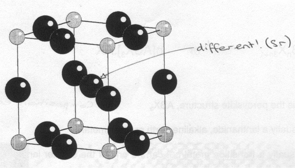
(showing the atoms in one unit cell).
If rA/rB is too small, then A doesn’t “fill” the hole at the centre of the unit cell and the octahedral title, usually (not always) lowering the symmetry to orthorhombic. The lowering of the symmetry has consequences for the properties of the material. If A is too large, then the structure undergoes a more drastic change.
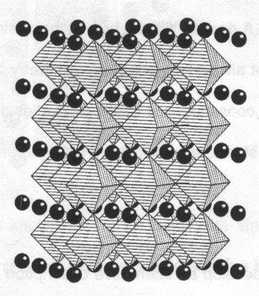
The unit cell view enables us to develop an alternative description of the structure, i.e. the cubic perovskite structure can be considered to be built up from pseudo-close packed planes of stoichiometry AO3, stacked in a CCP manner perpendicular to the [111] axis (body diagonal) of the unit cell. The B cations occupy the octahedral sites formed by oxide ions in successive planes, as shown:
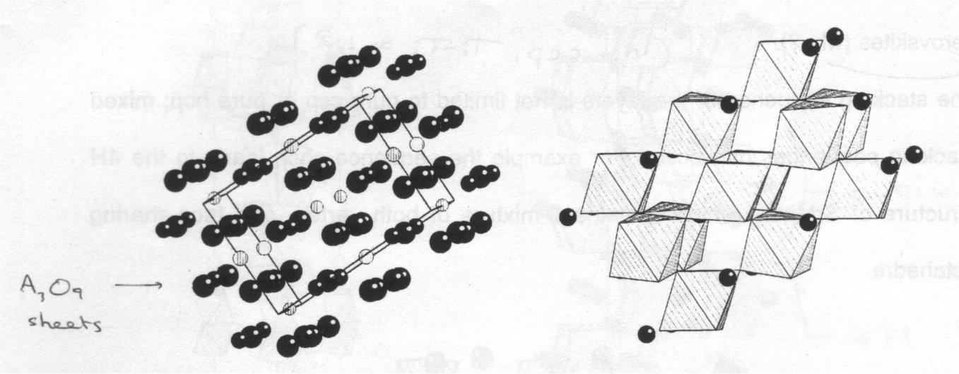
If the planes can be stacked in a CCP (ABCABC) fashion, they can also be stacked in a HCP (ABABAB) manner:

This is known as the 2H perovskite structure, because there are 2 AO3 layers in each unit cell. It looks very different from the cubic structure, comprising of isolated chains of face-sharing BO6 octahedra rather than a 3D array of vertex-sharing octahedra. The lowering of dimensionality of the crystal structure can have a wide range of interesting consequences for the physical properties of the material. The 2H structure involves a short B-B distance, and is rare in oxide chemistry, but more common amongst the halide perovskites, as X- can close in and shield the electrostatic repulsion from B:B.
The stacking sequence of the layers is not limited to pure HCP or CCP – mixed stacking sequences can also occur. This leads to structures such as the 4H of SrMnO3, which contains a mixture of both vertex and face sharing octahedra:
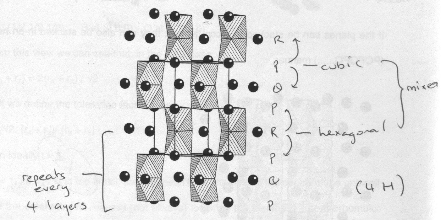
Many compounds adopt different stacking sequences as a function of temperature and pressure. Compounds with a mixture of atoms on the B sites, i.e. AB1-xB’xO3 move from the structure of ABO3 to that of AB’O3 in a complex manner.
If a cubic perovskite has two different elements on the B sites, then the cations can either occupy the sites at random, or an ordered manner. The latter is likely to increase the size of the unit cell by a factor of 2 (usually). The most common type of ordering is the 1:1 (i.e. alternating), which occurs in e.g. Sr2ErRuO6. Ordering is most likely to occur when the 2 species different significantly in size. Charge difference is also a factor, as is effects such as Jahn-Teller distortion (i.e. coordination requirements). The ordering has important effects on the physical properties, e.g. Sr2ErRuO6 shows long-range magnetic order at low temperatures, whereas Sr2FeRuO6 does not.
These systems are usually investigated by a combination of analytical techniques:
- Volumetric analysis to get the total oxygen content.
- X-ray diffraction to identify the basic structural type.
- Neutron diffraction to get the distribution of vacancies on the oxide sub-lattice.
- 57Fe Mossbauer spectroscopy to get the Fe3+/Fe4+ ratio.
- Electron microscopy to look at the regularity of the stacking sequence.
- etc…
Compounds having the perovskite structure show a wide range of useful and interesting physical properties:
- Dielectrics and ferroelectrics of oxides are used in capacitors e.g. barium titanate. Modification (e.g. by substitution) can lead to a structural phase transition which can leave the tetravalent transition metal cation in an irregular environment.
- Perovskites with incomplete oxide sub-lattices can be used a solid state electrolytes in fuel cells. An example is La1-xSrxGa1-yMgyO3-(x+y)/2.
- Catalysis, e.g. LaCr1-xNixO3.
- High temperature superconductors (discussed already).
- Mixed valence Mn perovskites are at the heart of current interest in colossal magnetoresistance.
Note that many of these involve anion vacancies and the degree of organisation of these is crucial in determining the properties.
Formation of Ruddlesden-Popper phases with n greater than 3 or less than infinity are difficult. The n=2 structure (e.g. Sr3Ti2O7) has only one type of B site but two distinct A sites. This is of particular interest in colossal magnetoresistance.
N=1 structures (K2NiF4) have one type of a site and one type of B site. However, it can accommodate a wide range of cations in bizarre combinations to achieve desirable properties (e.g. perovskite superconductors).
Superconductors
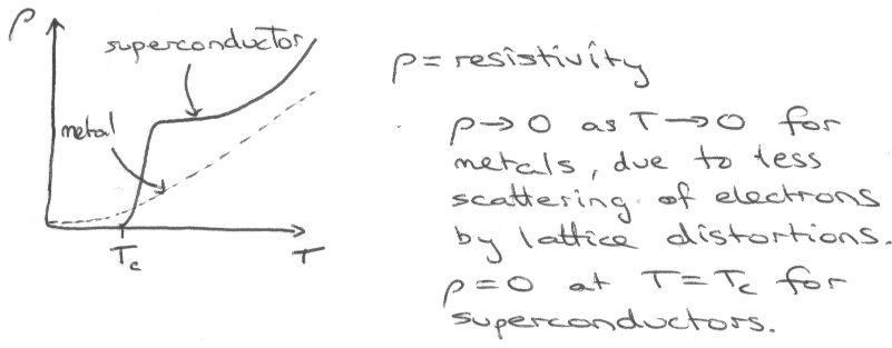
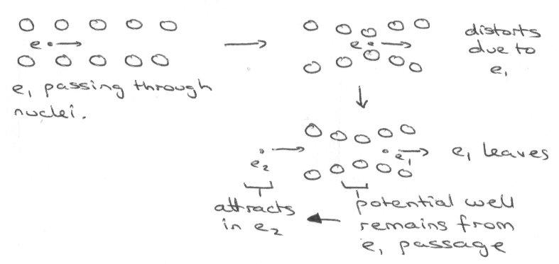
In a conventional metal the mobile conduction of electrons are scattered in their passage through the solid as a result of deviations in the positions of the atoms from the ideal positions of a perfectly periodic lattice. The deviations can arise from impurities, but even in a perfectly pure metal above 0K, the fluctuations in atomic positions due to thermal population of excited lattice vibrational states (called phonons) results in scattering of conduction electrons. Thus in an idealised “pure” metal resistivity increases with increasing temperature and there is increasing thermal population of excited phonon states. As T tends toward zero the resistivity decreases continuously and in principle extrapolates toward 0 at 0K. However in any “real” metal, impurities give rise to a non-zero resistivity as we tend toward 0K.
Superconductivity is a remarkable phenomenon in which the resistivity drops discontinuously to zero below a critical temperature Tc. The resistivity in the superconducting states is not just very low – it is exactly zero and current induced in a superconductor will flow without decay even in the absence of an applied voltage. Unlike zero conductivity in pure normal state metals, superconductivity is not restricted to idealised pure samples: even impure samples exhibit the phenomenon.
The onset of superconductivity is accompanied by expulsion of any lines of magnetic flux that run through the sample in the normal state. This phenomenon gives rise to perfect diamagnetism and is known as the Meissner Effect.
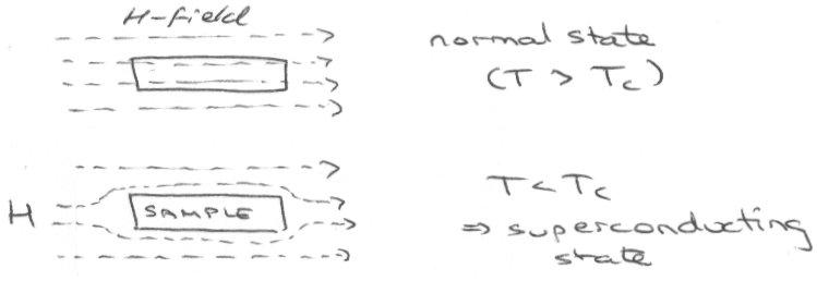
Flux can eventually enter for some superconductors, particularly Cuprates, and it then ceases to superconduct.
Theories to explain the phenomenon are mathematically complex, and although superconductivity in elements and alloys has been satisfactorily explained, there is still no strong theory on why the effect occurs at the much higher temperature for perovskite based cuprates.
Superconducting Materials
Superconductivity was first discovered in solid Hg, but an increasing number of elemental metals have been shown to exhibit it – most recently Li under high pressure, which now holds the record for the highest Tc in an elemental material.
A large number of alloys or binary compounds between a metal and a member of groups 13-15 also exhibit superconductivity. The most widely used material in superconducting magnets is Nb3Ge with Tc just above 23 K. However, following the recent discovery of superconductivity in MgB2 with Tc close to 40K, it is likely that this compound will displace Nb3Ge. MgB2 is a simple compound in which B22- sheets isostructural and isoelectronic with the sheets in graphite are separated by Mg2+ cations.
Critical Currents and Critical Fields
The perfect diamagnetism arises from screening currents which flow in the skin of the superconductor over a depth range known as the penetration depth. These currents generate a magnetic field which opposes any applied field to ensure that the magnetic flux density inside the superconductor is zero. The zero resistivity of the superconducting state persists only up to a critical value. Above the critical current zero resistivity is quenched, and the material returns to its normal state. As the magnetic field applies increases the magnitude of the screening currents required to sustain perfect diamagnetism increases. If the applied field exceeds the critical value it will return to the normal state. Both critical currents and critical fields decrease with increasing temperature and reach zero at the superconducting transition temperature.
Type I and Type II superconductors
Pure elemental superconductors e.g. Hg, are type I, whereas most alloy systems and compound materials are type II. For a type I superconductor, the internal magnetic flux density (induction) jumps discontinuously from zero to a value when the critical field is reached. At the same time the induced magnetisation due to screening currents drops suddenly to zero. For type II, lines of magnetic flux begin to break into the superconductor when a lower critical field is reached. Superconductivity is destroyed in rods of material through the flux penetrates but the material in between remains superconducting. Eventually superconductivity will be completely destroyed when the upper critical field is reached.
Bardeen Cooper Schrieffer Model
In the BCS Model, charge is carried by 2 electrons coupled together (Cooper pairs) not 1 electron. This is surprising since 2 x electrons normally repel!
The Cooper pair has zero spin so obeys Bose-Einstein statistics (it’s a Boson), so it can enter the same quantum state so the “gas” of paired electrons in the superconducting state is a macroscopic quantum object. Below Tc, thermal energy is insufficient to overcome the attractive interaction, so current carriers are not scattered by thermal vibrations (zero DC resistivity).
A consequence of the attractive pairing of the electrons is that there is a well-defined gap between the ground state of the system and excited states in which the pairs are broken. This gap ΔE has a magnitude of the order of kTc at 0K and can be observed directly by infrared or photoelectron spectroscopy. The magnitude of the gap decreases with increasing temperature and vanishes at Tc.

The diagram above comes about from interactions between lattice and electron vibrations. This would predict an isotope effect on interchange, and also that Tc increases as the number of electrons close to the Fermi energy increases. Both these are shown well by superconducting K3C60. The BCS Model also works for “standard” superconductors such as Nb3Ge and MgB2.
In the superconducting cuprates the charge carriers are again zero spin pairs of electrons, but these materials exhibit no isotope effect and the mechanism of the pairing appears not to involve lattice vibrations. The mechanism for the pairing in cuprates remains a matter of research and controversy.
BCS Theory –
Cooper pairs formed by attractive electron-electron interaction mediated by lattice vibrations (phonons):
kBTc = hω exp (-1/λ),
λ = VN(Ef)
- λ is the electron-phonon coupling constant.
- ω is the frequency of the lattice vibration that couples the electrons.
- V is strength of the electron-phonon interaction.
- N(Ef) is the density of states at the Fermi energy, i.e. the number of electronic states per unit energy range at the highest occupied energy in the solid. It is simply the number of states available to take part in the coupling.
- Sensible values of the parameters in the BCS equation give a maximum value of Tc of about 30K.
- Size of Cooper pair is about 1000A. The pairs are formed at Tc.
Perovskite-based High Temperature Superconductors
e.g. YBa2Cu3Ox , La2-xBa2CuO4.
As mentioned, it is not followed by the cuprates. For these, charge carriers are zero-spin electron pairs, but there is no isotope effect so the mechanism does not involve lattice vibrations. This is still being researched.
Also, BCS Model predicts a maximum Tc of ~40K, whereas these “high” temperature superconductors have been made to superconduct at ~ 150K (HgBa2Ca2Cu3O8+δ).
They can be considered as modified Ln2CuO4 (which is a Mott-Hubbard insulator), and then doping splits into bands of CuI/CuII and CuII/CuIII (filled) via oxidation and reduction by the doping agent. This gives holes and electrons respectively, and promotes electron hopping.
The Cooper pair formation is thought to be due to extremely strong superexchange interactions between Cu spins (not electron vibrations as this would give rise to lattice distortions).
Zeolites
Also called Molecular Sieves. They are aluminosilicates of general formula: (Mm+)y/m(SiO2)x(AlO2)y.nH2O with open framework structures. Up to 50% of the volume may be void. The lower charge on Al as compared to Si is compensated by extra-framework cations Mm+.
|
Name |
Type |
Si:Al ratio |
|
Zeolite-A |
LTA |
1 : 1 |
|
Zeolite-X |
FAU |
1.2 : 1 |
|
Faujasite |
FAU |
2.5 : 1 |
|
Chabazite |
CHA |
2 : 1 |
|
ZSM-5 |
MFI |
31 : 1 |
|
Silicalite |
MFI |
∞ |
Zeolites are based on corner sharing SiO4 or AlO4 tetrahedra. The Si-O-Si angles can be close to 180o in some cases.
Zeolites are prepared from solutions containing sodium silicates and aluminates, [Al(OH)4]-, at high pH. A gel forms by a process of copolymerisation of these ions. The product obtained is determined by the conditions chosen. Silicon rich synthetic zeolites are much more easily synthesised using templates such as large quaternary ammonium cations instead of Na+. The synthesis of zeolites relies on hydrothermal methods as discussed above. This is because crystallisation process is frequently slow and hydrothermal methods act to speed up the process.
ZSM-5 – a mixture of silicic acid, NaOH, aluminium sulphate, water, n-propylamine and tetrapropylammonium bromide is heated in a hydrothermal bomb at 160oC for several days. The organic template ion directs the formation of the structure with the alkyl groups filling the channels. The template ion may be removed from the cavity by heating the product in air, oxidising the organic cation and leaving intact the aluminosilicate framework.
Zeolite-A – has small pores.
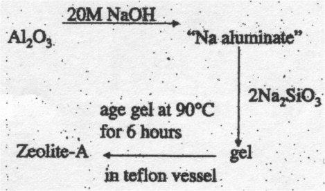
Larger pore sizes may be promoted by using a larger cation as a template. Growth of zeolites from the gel may be promoted by carrying out the reaction in sealed teflon bombs.
Problems of Structure Determination for Zeolites –
- Large unit cells.
- Si and Al look the same to X-rays.
- Large number of sites for extra-framework cations. May be disordered.
- Disordered water or solvent in supercages.
- Only available of polyx or microcrystalline material.
Methods Used –
- High quality powder X-ray Diffraction.
- Powder Neutron Diffraction.
- Single crystal diffraction on microcrystals (with synchrotron X-rays).
- Solid State NMR.
- Atomistic simulation.
Applications of Zeolites
- Selective absorption of molecules discriminated by size – molecular sieves.
- Zeolite-A will absorb O2 and H2O but not C2H5OH – can be used as a drying agent.
- Ion Exchange – extra framework Na+ cations can exchange with other cations (especially if carrying a higher charge).
- Clean up of radioactive Sr2+ isotopes after Chernobyl.
- Washing powder contains Na zeolite-A. Exchanges with Mg2+ and Ca2+ to soften water. Degrades to soil-like residue, in contrast to polyphosphates.
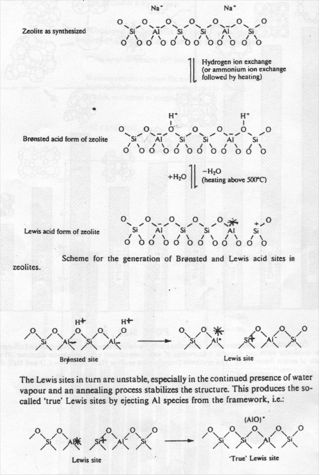
Acid catalysis
Exchange of the extra-framework species for cations yields Bronsted sites, convertible to Lewis and “true” Lewis acid sites on heating:
Shape Selective Catalysis

Mesoporous Solids
Recently workers at Mobil prepared ordered arrays of pores in the 20-100A range in the MCM-41 class of “mesoporous” silicate solids. In this case, the template is not a single molecule, but a self-assembled molecular array – “liquid crystal templating”.
Thin Film Single Crystals
Generally these are formed between a group 13 and group 15 element (III-V semiconductors), and group 12 and group 16 (II-VI semiconductors).
|
Group IV elements (with diamond structure) |
III-V compounds with wurtzite structure |
III-V compounds with zinc blende structure |
II-VI compounds with zinc blende structure |
|
C – 5.4eV |
AlN – 6.02eV |
AlP – 2.45eV |
ZnS – 3.54eV |
|
Si – 1.107eV |
GaN – 3.34eV |
GaP – 2.24eV |
CdTe – 1.44eV |
|
Ge – 0.67eV |
InN – 0.7eV (Nov 2002) |
InP – 1.27eV |
HgTe – zero band gap |
|
α-Sn – 0.4eV |
|
AlAs – 2.16eV |
ZnSe – 2.58eV |
|
|
|
GaAs – 1.35eV |
ZnTe – 2.26eV |
|
|
|
InAs – 0.35eV |
|
|
|
|
AlSb – 1.6eV |
|
|
|
|
GaSb – 0.67eV |
|
|
|
|
InSb – 0.163eV |
|
The Group IV elements have an indirect energy gap, while the compounds with the Zinc Blende structure have a direct energy gap.
Applications of III-V and II-VI Materials
- GaAs offers potential of ultrafast electronic devices (transistors, integrated circuits, etc.) because electron mobility is much higher in GaAs than Si.
- Devices integrating electronics with optics (direct energy gap).
- Lasers based on p-n junctions or quantum wells. The quest is for materials operating in the blue or green, with promising candidates being GaN or ZnSe or “alloy” materials such as Zn1-xMgxSe1-ySy.
- Infrared photoconductivity detectors. Here we need a narrow energy gap – the lower the gap the longer the wavelength that can be detected, but the lower the temperature of operation needs to be in order to minimise thermal excitation of charge carriers across the energy gap. Favourite materials are InSb or InSb1-xAsx or Cd1-xHgxTe.
Band Gap Engineering
Many III-V (or II-VI) compounds form a wide range of solid solutions (sometimes called “alloys”) with other III-V (or II-VI) compounds with a different band gap. The Band gap can be tuned between the limits of the two compounds by varying the alloy composition.
For example,
Hg1-xCdxTe (mercury cadmium telluride, or MCT). Band gap tuned up from 0eV through to 1.44eV by Cd alloying. Very useful for IR detectors.
Ga1-xAlxAs. Band gap increases from 1.35eV with increasing Al incorporation. Band gap engineering in this system is widely used for GaAs based heterostructures.
InSb1-xAsx. Limiting band gaps of InSb and InAs are 0.163eV and 0.35eV. Unusually, band gap passes through a minimum of about 0.13eV with 10% incorporation of As.
Physical Methods of Preparation
- Molecular beam epitaxy (MBE).
Uses thermal beams of vapours of Group III and Group V elements in ultrahigh vacuum apparatus, e.g. Ga(g) + As(g) → GaAs(s).
Problems:
Most group V elements vapourise as tetrameric species (e.g. P4). These can be thermally cracked to give dimers which have a higher sticking coefficient on the growing surface.
Cracking of N2 for nitride growth very difficult – need to use radiofrequency or microwave plasma sources rich in N atoms.
Need lattice matched substrate for growth of true single crystal layers.
- Metallo-organic molecular beam epitaxy (MOMBE).
- Chemical beam epitaxy (CBE).
Both these techniques use volatile precursors but again in ultrahigh vacuum apparatus.
For example, Ga(CH3)3 (g) + AsH3 (g) → GaAs(s) + 3CH4(g).
n-type doping with Te on As sites using H2Te or Si on Ga sites using SiH4.
- Metallo-Organic Chemical vapour deposition (MOCVD).
- Metallo-Organic Vapour phase epitaxy (MOVPE).
Uses volatile precursors in ambient pressure reactor.
- Pulsed laser deposition (PLD).
- Laser ablation.
Laser ablation of a target by rapid heating of a surface produced by a pulsed UV laser.
I am happy for them to be reproduced, but please include credit to this website if you're putting them somewhere public please!